Original training media · Public preview

Field concepts, made visible.

These original TTS figures are being developed with our engineering team for the 100-series building-automation foundation. They connect refrigeration, air systems, controls, electrical concepts, sensors, and actuators before learners work through guided labs.

Review status: These figures are conceptual learning aids, not construction drawings, code documents, manufacturer instructions, or authorization to perform regulated work. Final course use is subject to instructor, technical, accessibility, and safety review.
100-series figure set

Eight diagrams ready for instructional review.

Select a figure to open the scalable version. Source files and course answer material remain private; only approved learning graphics appear in this preview.
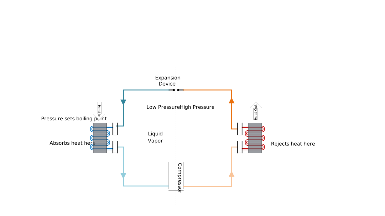
Refrigeration cycle diagram showing major components and refrigerant state changes
F-102-ARefrigeration cycle

Connects the compressor, condenser, metering device, and evaporator to pressure, temperature, and change of state.
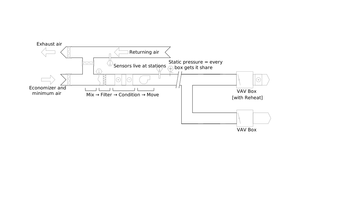
Air-handling unit airflow path through filters, coils, fan, and duct system
F-102-BAir-handling airflow

Traces air through the major sections of an air-handling system and establishes where control points affect delivered conditions.
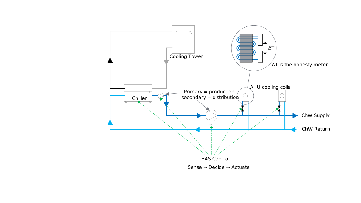
Central plant diagram connecting chilled water and condenser water systems
F-102-CCentral plant relationships

Shows how plant equipment, water loops, loads, and heat rejection work together as one controlled system.

Electrical control circuit and meter relationship training diagram
F-103-AControl circuits and measurement

Introduces circuit relationships and meter thinking while reinforcing qualified-person boundaries and safe procedures.
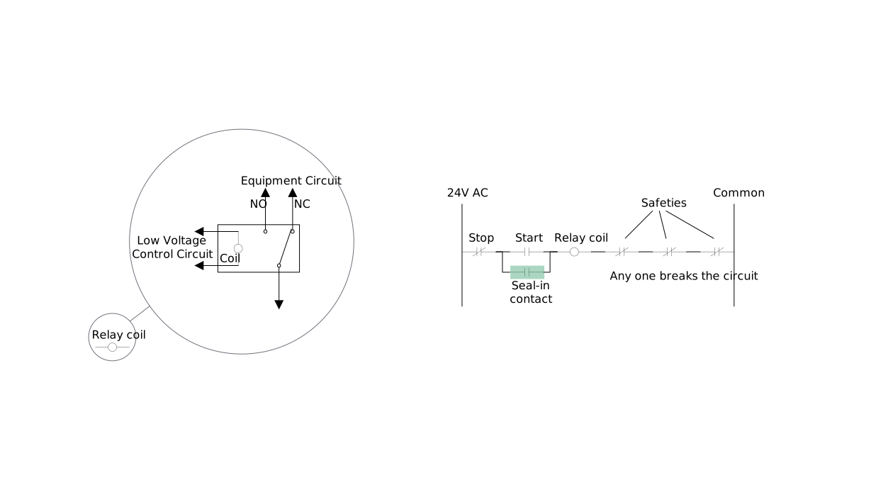
Relay and ladder logic training diagram with contacts and coil
F-103-BRelays and ladder logic

Connects physical relay behavior to ladder diagrams, enabling conditions, commanded state, and proof.
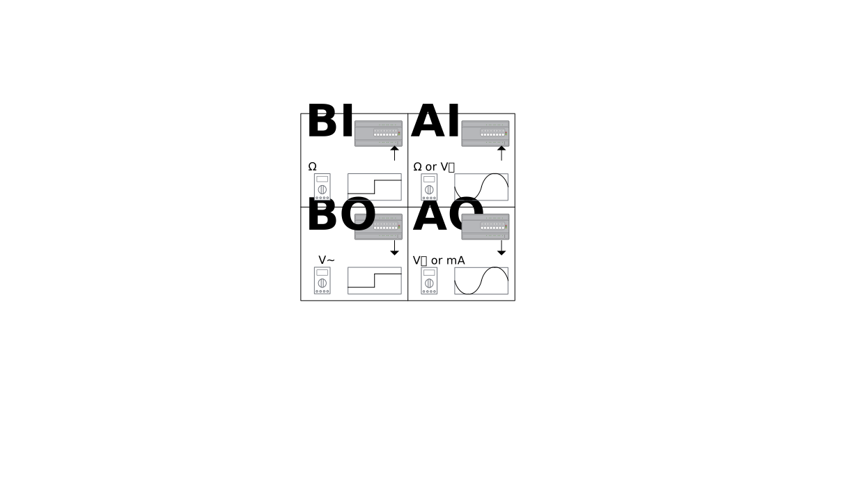
Building automation input and output signal relationship diagram
F-103-CBAS input and output relationships

Maps sensors, binary states, controller logic, and outputs to the equipment they monitor or command.
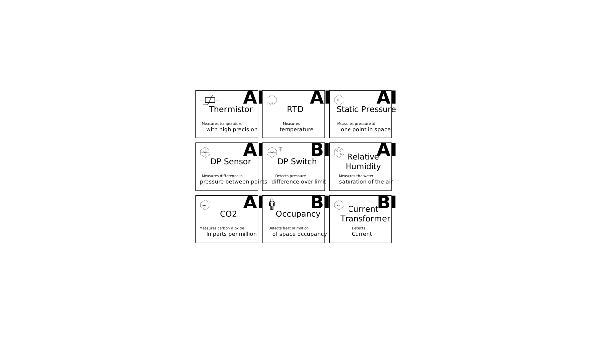
Sensor families used in building automation systems
F-104-ASensor families

Organizes common sensing technologies by the physical condition being measured and the signal a controller receives.
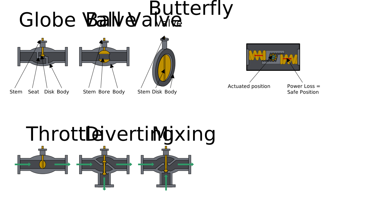
Actuator, valve, and damper application training diagram
F-104-BActuators, valves, and dampers

Connects controller output to mechanical motion, flow control, feedback, and field verification.

Instructional boundary: Learners use these figures with course procedures, equipment documentation, applicable codes, and qualified supervision. Diagrams never replace lockout/tagout, energized-work rules, refrigerant-handling requirements, site procedures, or manufacturer instructions.